01
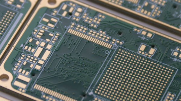
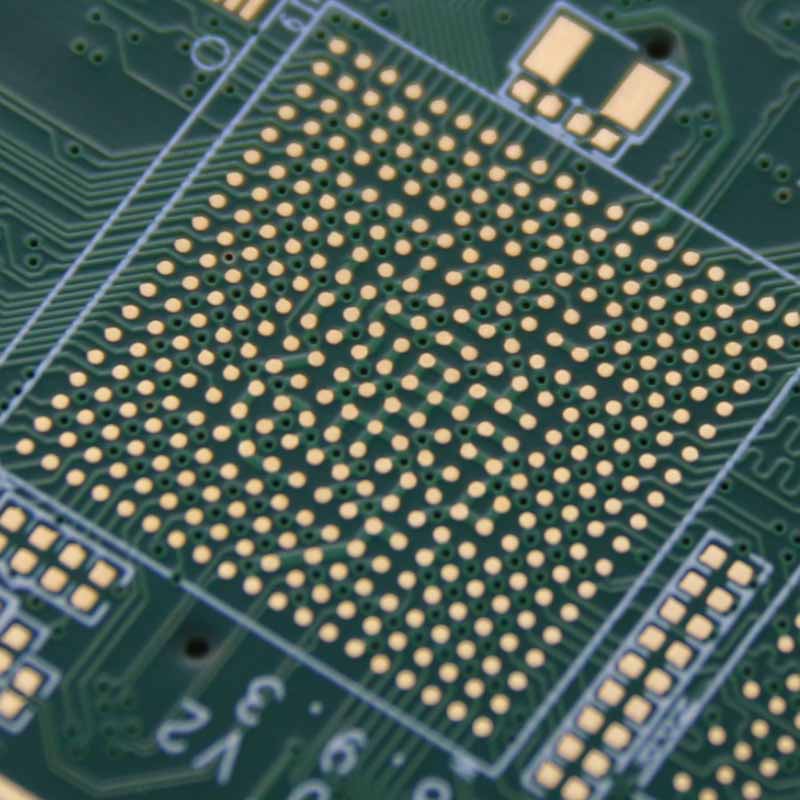
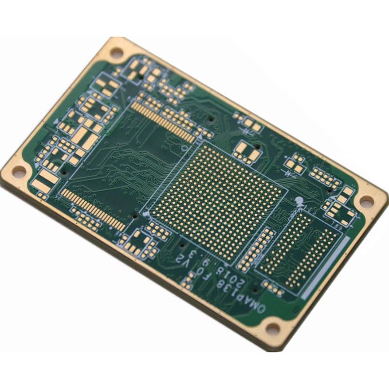
Immersion Gold Surface Finishing


There are 6 different types of HDI boards, through vias from surface to surface, with buried vias and through vias, two or more HDI layer with through vias, passive substrate with no electrical connection, coreless construction using layer pairs and alternate constructions of coreless constructions using layer pairs.
| Item | Manufacturing Capabilities | Remark | ||||||
| Material | ||||||||
| Material | Shengyi FR-4 | Normal TG, Medium TG and High TG | ||||||
| HF | Medium TG and High TG | |||||||
| Ceramic filled High Frequency Board | Rogers 4003/4350, Arlon 25N/25FR | |||||||
| PTFE High Frequency Board | Rogers series, Arlon series, Taconic series | |||||||
| Specification | ||||||||
| Surface Finish | HASL with Lead/HASL LEAD FREE | Tin Thickness | 2-40um | |||||
| Board Thickness | 0.6mm≤H≤3.0mm | |||||||
| Immersion Gold (ENIG) | Max. Gold Thickness | 8u" | ||||||
| OSP | Film Thickness | 0.2-0.5um | ||||||
| Hard Gold | Max. Gold Thickness | 2.0um | ||||||
| Immersion Tin | Tin Thickness | 0.8-1.2um | ||||||
| Immersion Silver | Silver Thickness | 0.15-0.25um | ||||||
| Layers | 4 - 40 layers | FR4 Max. 40 layers | ||||||
| Finished Board Thickness | 0.2-6.8 mm | Min. Thickness: 0.2mm (Double-Sided) | ||||||
| Thickness Tolerance | T≥1.0mm | ±10% (Standard PCB) | ±8% (Advanced PCB) | / | ||||
| T<1.0mm | ±0.1mm (Standard PCB) | ±10% (Advanced PCB) | / | |||||
| Finished Copper Thickness | 1oz/2oz (Standard PCB) | Inner Layer: 12oz (Advanced PCB) | 1oz = 35um | |||||
| Outer Layer: 15oz (Advanced PCB) | ||||||||
| Bow and Twist | Per Cater-Corner Length, ≤0.75% (Standard PCB) | ≤0.50% (Advanced PCB) | For Boards without SMT, the max. 1.5% | |||||
| Drill | ||||||||
| PTH Deviation | ±3mil (Standard PCB) | ±2mil (Advanced PCB) | ||||||
| NPTH Deviation | ±2mil (Standard PCB) | ±1mil (Advanced PCB) | ||||||
| Hole Position Deviation | ±3mil (Standard PCB) | / | ||||||
| Hole Wall Roughness (Max.) | 1.5mil (Standard PCB) | 1mil (Advanced PCB) | ||||||
| Min. Drilling Bit Diameter | 0.3mm (Standard PCB) | 0.25mm (Advanced PCB) | ||||||
| Max. Drilling Bit Diameter | 6.5mm (Standard PCB) | / |
For vias larger than 6.5mm, multiple drilling or milling is recommended |
|||||
| Min. Slot Width | 0.6mm (Standard PCB) | / |
For HASL, the min. finished slot width is 0.45mm, for other surface finish, it is 0.5mm |
|||||
| Board Thickness/Via Diameter | ≤6:1 (Standard PCB) | ≤7:1 (Advanced PCB) |
7:1≤value≥6:1, add one more day for fabrication |
|||||
| PTH Deviation | Width | ±4mil (Standard PCB) | / | |||||
| Length | ±5mil (Standard PCB) | / | ||||||
| NPTH Deviation | Width | ±3mil (Standard PCB) | / | |||||
| Length | ±4mil (Standard PCB) | / | ||||||
| Hole Wall Copper Thickness | Thinnest | ≥0.71mil (Standard PCB) | ≥1mil (Advanced PCB) | |||||
| Average | ≥0.8mil (Standard PCB) | ≥1mil (Advanced PCB) | ||||||
| VIA Space (Same Net) | ≥8mil (Standard PCB) | ≥6mil (Advanced PCB) | ||||||
| VIA Space (Different Net) | ≥17mil (Standard PCB) | ≥14mil (Advanced PCB) | ||||||
| Min. Space for Component VIAs in Different Net | ≥24mil (Standard PCB) | ≥20mil (Advanced PCB) | ||||||
| Max. PTH | Round Hole | 8mm (Standard PCB) | 10mm (Advanced PCB) | |||||
| Slot Holes | 6*10mm (Standard PCB) | 8*12mm (Advanced PCB) | ||||||
| Trace | ||||||||
| Min. Trace Width/Space | 1oz | 6/6mil (Standard PCB) | 5/5mil (Advanced PCB) |
The space refers to the distance between trace to trace, trace to copper |
||||
| 2oz | 8/8mil (Standard PCB) | 7/7mil (Advanced PCB) | ||||||
| Min. SMD Width | 1oz | ≥10mil (Standard PCB) | ≥8mil (Advanced PCB) | / | ||||
| 2oz | ≥12mil (Standard PCB) | ≥10mil (Advanced PCB) | ||||||
| Space between Pad to Trace | 1oz | 8mil (Standard PCB) | 6mil (Advanced PCB) | / | ||||
| 2oz | 8mil (Standard PCB) | 6mil (Advanced PCB) | ||||||
| Min. Etching Letters | ≥8mil (Standard PCB) | ≥7mil (Advanced PCB) | ||||||
| Min. Space for SMD | ≥10mil (Standard PCB) | / |
The data is the Min. space to achieve Solder Mask Bridge, if Bridge is not required, please refer to the Min. Trace Space requirement |
|||||
| V-Cut Line to Copper | T≥1.5mm, V-Cut 20° | 20mil (Standard PCB) | 16mil (Advanced PCB) | |||||
| T≤1.2mm, V-Cut 20° | 16mil (Standard PCB) | 12mil (Advanced PCB) | ||||||
| Trace Width/Space Deviation | ±20% (Standard PCB) | ±15% (Advanced PCB) | ||||||
| Trace Net Grids | 12/12mil (Standard PCB) | 8/8mil (Advanced PCB) | ||||||
| Alignment Accuracy for Layer | ±3mil (Standard PCB) | ±2mil (Advanced PCB) | ||||||
| Space between Trace and Border | Inner layer | ≥16mil (Standard PCB) | ≥12mil (Advanced PCB) |
If there is V-Cut requirement, please follow the V-Cut standards |
||||
| Outer layer | ≥10mil (Standard PCB) | ≥8mil (Advanced PCB) | ||||||
| Space between Via to Trace | ≥12mil (Standard PCB) | ≥10mil (Advanced PCB) | ||||||
| Space between Inner Via to Trace | ≥10mil (Standard PCB) | ≥8mil (Advanced PCB) | ||||||
| Solder Mask | ||||||||
| Solder Oil Thickness | Trace Interface | 0.4-0.8mil (Standard PCB) | / | |||||
| Trace Corner | ≥0.2mil (Standard PCB) | / | ||||||
| Plugged Via Diameter | Plugged on both sides | ≤0.45mm (Standard PCB) | 0.5-0.55mm (Advanced PCB) |
No solder mask opening on both sides |
||||
| Plumpness for Plugged Vias(Max.) | 100%(Vias Diameter≤0.4mm) (Standard PCB) | 50%(Vias Diameter≤0.45mm) (Advanced PCB) | Refer to plugged depth | |||||
| Space between Opening to Trace/Copper | ≥4mil (Standard PCB) | ≥3mil (Advanced PCB) | ||||||
| Opening Size (Single Side) | ≥3mil (Standard PCB) | ≥2mil (Advanced PCB) | ||||||
| Text Width for Solder Mask Opening | ≥10mil (Standard PCB) | ≥8mil (Advanced PCB) | ||||||
| Solder Mask Bridge Width | Green, Blue≥4mil; White, Black≥6mil; others≥5mil | |||||||
| Silkscreen | ||||||||
| Silkscreen Width | Positive Text | ≥6mil (Standard PCB) | 5mil (Advanced PCB) | |||||
| Negative Text | ≥8mil (Standard PCB) | ≥6mil (Advanced PCB) | ||||||
| Silkscreen Height | ≥40mil (Standard PCB) | ≥30mil (Advanced PCB) | ||||||
| Space between Silkscreen to Copper Pad | ≥7mil (Standard PCB) | 6mil (Advanced PCB) | ||||||
| The Distance between Solder Mask Oil to Copper Pad | ≥10mil (Standard PCB) | 8mil (Advanced PCB) | The Min. Solder Mask Oil Strip is 5mil | |||||
| Space between Silkscreen to Border | ≥8mil (Standard PCB) | 6mil (Advanced PCB) | ||||||
| Min. Silkscreen Space | ≥6mil (Standard PCB) | 5mil (Advanced PCB) | ||||||
| V-CUT | ||||||||
| Min. Dimension | 80*80mm (Standard PCB) | / |
Only for V-Cut with one direction, the min. size is 40mm for the side without V-Cut |
|||||
| Max. Dimension | 500*500mm (Standard PCB) |
Max. Width for manual V-Cut board is 500mm, not limited for length |
||||||
| Min. Board Thickness | 0.6mm (Standard PCB) | / | No V-cut for 0.4mm board | |||||
| V-CUT Angle | 20°/30° (Standard PCB) | / | ||||||
| Alignment Accuracy for Neighbouring V-CUT | ±0.1mm (Standard PCB) | / | ||||||
| Space for two V-CUT Lines | ≥3mm (Standard PCB) | / | ||||||
| Space between Border to first V-Cut Line | ≥3mm (Standard PCB) | / | ||||||
| Remaining Board Thickness after V-Cut | 1/3 or 1/4 of Board Thickness (Standard PCB) | / | Min. remaining thickness 0.25mm | |||||
| Remaining Board Thickness Deviation after V-Cut | ±0.1mm (Standard PCB) | / | ||||||
| Profiling | |||||||
| CNC Routing Deviation | ±0.15mm (Standard PCB) | ±0.10mm (Advanced PCB) | |||||
| CNC the Distance Deviation between Via to Border | ±0.13mm (Standard PCB) | ±0.10mm (Advanced PCB) | |||||
| Min. Slot Width | 0.8mm (Standard PCB) | / | |||||
| CNC Min. Via Corner Angle for Routing | 0.4mm (Standard PCB) | / | |||||
| Min. PCB Dimension | 5*5mm (Standard PCB) | Min. 3mm for one side (Advanced PCB) | |||||


More over 1,150 customers cooperated with Our.
Contact us now
you will get the Bonus worth $350 for PCBA free sample.

JINGHON ELECTRONICS LIMITED is founded in 1998, With a qualified, experienced and dedicated team of professionals, JINGHON ELECTRONICS LIMITED is able to provide a full compliment of services to our clients with a complete systems design, build, integration and after-sales support.
Copyright ©JINGHON ELECTRONICS LIMITED | All Rights Reserved